| Empty Weight | $440,000 for each 100 lbs overweight |
| Acceleration | $440,000 for each second slow |
| Escort Radius | $1 million for each 10 nautical miles short |
| Approach Speed | $1.056 million for each knot fast |
| Maintainability | $450,000 for each extra maintenance man-hour per flight hour |
| Delivery to Navy Board of Inspection and Survey | $5,000 for each day late |
| With this background and a good deal of knowledge on building Navy fighter aircraft, Grumman
succeeded in delivering the F-14 on time, on cost and as an even better fighter than they
contracted for! |
| 303-60 |
|
The January 1968 proposed aircraft |
Podded Engines, High Variable-Sweep Wing |
| 303A |
|
Nacelle Modification of 303-60 |
Podded Engines, High Variable-Sweep Wing |
| 303B |
 |
Design 303-60 updated for configuration comparison |
Podded Engines, High Variable-Sweep Wing |
| 303C |
 |
|
Submerged Engines, High Variable-Sweep Wing |
| 303D |
 |
|
Submerged Engines, Low Variable-Sweep Wing |
| 303E |
 |
Basically, the winning F-14 design |
Podded Engines, High Variable-Sweep Wing |
| 303F |
 |
|
Submerged Engines, High Fixed Wing |
| 303G |
|
A fighter only version (AWG-10, 4 Sparrows) without Phoenix
capability |
Podded Engines, High Variable-Sweep Wing |
When the initial design 303E was accepted, further improvements were made in
the next design steps:
|
| Improvements |
Advantages |
| Incorporation of Grummans convergent-divergent iris engine nozzles. |
Increased supersonic maximum afterburner thrust at no penalty in cruise
fuel flow. |
| Nacelles moved closer together and fuselage depth increased forward. |
Reduced wetted area and improved area distribution. - Better sinle-engine
control. |
| Revised lines (reflexed trailing edge) of internacelle "pancake"
area. |
Reduced negative supersonic zero-lift pitching moment and reduced supersonic
trim drag. |
| Wing area increased to 565 square feet from 505 square feet. |
Increased combat agility. - Allowed use of simple hinged single-slotted
flap, rather than complex double-slotted extensible flap. As a fallout,
maneuvering flap is easily achieved. |
| Reduced wing aspect ratio, from 8.15 to 7.28. |
Aspect ration 7.28 yielded minimum takeoff gross weight for Navy-specific
(TS-161) fighter mission while still meetin TS-161 6-Phoenix Combat Air
Patrol mission carrier-suitability requirements. |
| Re-evaluation of wing bending moments. |
Considerably reduced design static wing bending moments. |
| Addition of Mach Sweep Programmer |
Further reduced design static wing bending moments. - Optimum sweep
programming assured pilot of maximum combat agility he would lack with
fixed-sweep combat detent or fixed-wing aircraft. - Reduced engineering
and flight test development costs. |
| Incorporation of Direct Lift Control for carrier approach. |
Better control of approach glide path with greatly reduced angle-of-attack
excursions. - Reduced variability of deck contact conditions, such as attitude
and sink rate. |
| Incorporation of glove vane. |
Superior supersonic maneuverability. - Reduced supersonic trim drag. |
| Improved treatment of wing/nacelle relationships involving wing dihedral
inboard and anhedral outboard. |
Better wing/nacelle sealing in all sweep positions. - Improved mechanization
of over-wing fairing covers. |
The first flight of the No.1 prototype F-14A took place on December 21,
1970. All in all, fourteen aircraft were used for the development programm,
12 of them instrumented. Of those 12, two were used for the development
of the Hughes Phoenix Missile System at Hughes Aircraft Corporation at
Point Mugu, CA. Six aircraft were used for airframe/engine testing at the
Grumman facilities at Calverton, NY and four for avionic system development
at Pt. Mugu. Five F-14s (of the six "airframe" aircraft) spent
some time at Patuxent River, Maryland for carrier suitability trials and
for structural, powerplant and performance demonstration. The fully proven
F-14 was introduced to the fleet only 51 month after contract award!
|
|
 Click here to read a historic magazine article about the
Grumman F-14, dated November 1970. The aviation magazine article was published in the
INTERAVIA magazine. Or click here to take a look at
photos from early F-14 prototype testing and production.
Click here to read a historic magazine article about the
Grumman F-14, dated November 1970. The aviation magazine article was published in the
INTERAVIA magazine. Or click here to take a look at
photos from early F-14 prototype testing and production. |
|
Day 1, First Flight! |
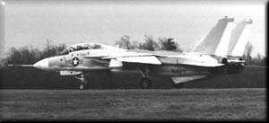 The photograph (click on it to view larger format picture!) shows No.1 prototype shortly before
its maiden flight on December 21st 1970.
Note the noseprobe, the larger stiffeners on the fuselage and the absence of the
gun. Also take a close look at the vertical stabilizer's top and its root modification.
On the aircrafts second flight, the no.1 Tomcat was lost due to
failure of a hydraulic pump which caused a total loss of flight controls. The crew managed to
eject safely and the aircraft crashed short of the runway at Grumman's Calverton facilities
in New York.
The photograph (click on it to view larger format picture!) shows No.1 prototype shortly before
its maiden flight on December 21st 1970.
Note the noseprobe, the larger stiffeners on the fuselage and the absence of the
gun. Also take a close look at the vertical stabilizer's top and its root modification.
On the aircrafts second flight, the no.1 Tomcat was lost due to
failure of a hydraulic pump which caused a total loss of flight controls. The crew managed to
eject safely and the aircraft crashed short of the runway at Grumman's Calverton facilities
in New York. |
|
| The story continues... Click here to read more about the Grumman prototype
F-14B, the F-14A+
(todays F-14B), the F-14C, F-14D and
F-14 derivatives for the future or click below to take a look at the F-14's specifications.
|

 F-14A
F-14A
 In 1968
the F-14 program was born with the Navy's proposal for the VFX (Navy Fighter Experimental) and
resulted in Grumman's general design 303 (see below). The VFX required a fighter with a two-man crew with
tandem seating, two engines, an advanced weapon system with a powerful radar plus the ability to
carry a variety of long-, medium- and short-range high-performance air-to-air missiles and an
internal gun.
Furthermore, the VFX should be able to land on a carrier with a full armament load (if one
considers the costs of todays weapons quite a reasonable requirement!). As an incentive for the
contractor to fullfill the requirements, the Navy put some penalties on the project if
Grumman would fail on some of the contract guarantees:
In 1968
the F-14 program was born with the Navy's proposal for the VFX (Navy Fighter Experimental) and
resulted in Grumman's general design 303 (see below). The VFX required a fighter with a two-man crew with
tandem seating, two engines, an advanced weapon system with a powerful radar plus the ability to
carry a variety of long-, medium- and short-range high-performance air-to-air missiles and an
internal gun.
Furthermore, the VFX should be able to land on a carrier with a full armament load (if one
considers the costs of todays weapons quite a reasonable requirement!). As an incentive for the
contractor to fullfill the requirements, the Navy put some penalties on the project if
Grumman would fail on some of the contract guarantees: