
MiG-21 Fuel System
The described fuel system is the one of the MiG-21US (Type 68, NATO Mongol B). However, it is very similar to the one used in MiG-21PF, MF, BIS except for differences in fuel quantity and annunciator light markings. I'll add the missing schematic at a later time.
Definitions:
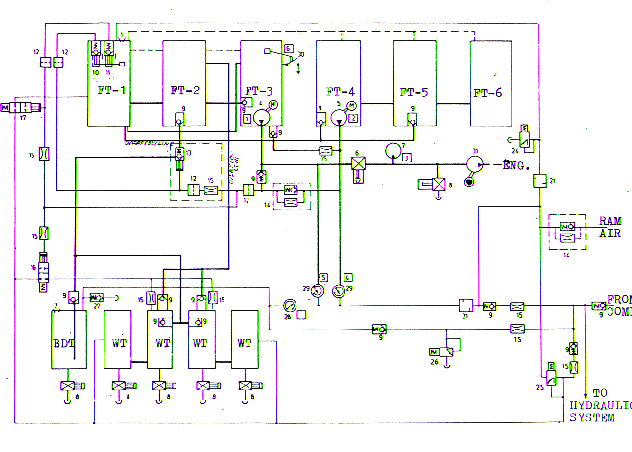
FT - Fuselage Tank
BDT - Belly Drop Tank
WT- Wing Tank
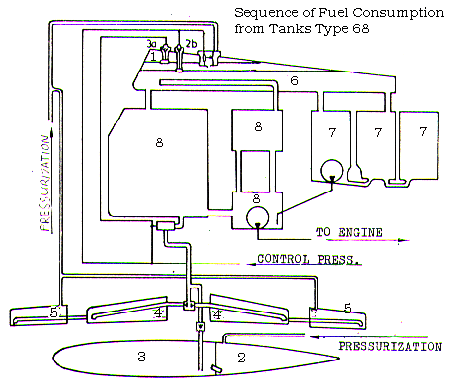
The fuel system consists of six FT's, four integral WT's, one BDT. The fuel tanks (No. 2 to No. 7) are located between bulkheads No. 7 and No. 28. They are made from two soft layers except for tank No. 7. The inner layer is from fuel-resistant rubber of 0.5 mm thickness and outer one is from rubberised fabric of l.l-29.5mm thickness. These "soft" tanks are located in special metal boxes.
The fuel system consists of two sub systems, these being the pressurization system and a control pressure system.
The pressurization system consists of a compressed bleed air which is fed to each of the eleven tanks. The pressure varies from tank to tank, highest pressure being bled to the BDT followed by the WT's and the FT's respectively. The system works under the principal that the fuel under highest pressure is transferred first. Two auxiliary fuel pumps are present in FT-3 and FT-4 and fuel flow is aided by an engine driven fuel pump tanks FT-1 and FT-3 are key to the operation of the system, FT-1 being a flow control unit and Ft-3 being the only tank from which fuel is transferred directly to the engine.
OPERATION and WORKING PRINCIPAL
The system pressurizes itself as soon as engine bleed air is present and initial fuel (about 70...100 liters) is taken only from Group-2 (FT-1...3). FT-1 incorporates pressurization float valves (#10, 11) which activate the fuel cock (13) as soon as fuel level in FT-1 drops 70...100 liters. The fuel cock is opened by the pressure control system which is directly linked to float valves. This sub system consists of a series of pressure lines which sense changing pressure at the float valves thereby controlling fuel transfer from the WT's and the BDT. The highest pressure is bled to the BDT thereby being the first tank consumed. Once empty fuel is transferred from the WT's to FT-3. This is accomplished by bleeding the next lowest pressure to the wing tanks. Fuel the flows through check valves (9) to the fuel cock (13) into FT-2, transferred to FT-3 and then pumped to engine. The consumption of fuel contained in Group-3 (FT-4...6) occurs in much the same way as the WT's except that transfer to FT- 3 is aided by an auxiliary fuel pump (5). Safety features include a network of overflow lines connecting Group-2,3, WT's and the BDT. The pressure limiters are also incorporated to prevent overboosting of the system. Emergency jettison of the BDT is done pyrotechnically.
| SEQUENCE OF FUEL CONSUMPTION | |||
|---|---|---|---|
| | |||
| drop tank | | ||
| 3. group | |||
| Reminder | | ||
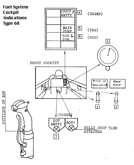
REMARKS / EMERGENCY PROCEDURES
...If "Group 3 Empty" already lights at 1300...1400 Liters means some trouble with the WT's. Actual fuel remaining for use is 170...850 Liters. Go to land and consider a higher weight due to the still full WT's. ...If one of the pump annunciator lights at a higher quantity than shown above, always check the switches. Afterburner-use with Main Pump in Off position can cause engine failure. ...In case of landing with fuel remaining of less than 200 Liters (52 Gallons) the "pump of group 3" should be on to use eventual unused fuel still in Group 3. The pump should work until the landing has been accomplished in this case...Flashing of the light "Main Pump" at altitudes higher than 45000 ft:
1. disengage afterburner; military power only!
2. rapidly descent below 45000 ft; then decrease power for further descent
3. Approach Airport for landing at 15000 ft or less
4. do not apply negative G-load