 |
 |
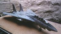
| Two views of the completed model. |
F-14 Model kit Review
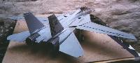
Fujimi 1/72nd Scale F-14A Plus "Checkmates"
|
|
| Two views of the completed model. |
After their initial series of F-14A kits Fujimi have produced several variants, some of which differ simply in the marking options offered while others represent later versions of the F-14. This review describes their first kit of the F-14A+ version.
Kit Type:Injection moulded plastic with metal parts and vinyl tyres
No of parts:157 (?)
Decal options:VF-211 Checkmates, low-vis markings for aircraft 'NG 111' BuNo:-163410
VF-24 Checkertails, low-vis markings for aircraft 'NG 200' BuNo:-163215. This aircraft also features a false canopy on the fuselage bottom.
VF-143, low vis markings for 'AG 111' BuNo:-163220. This aircraft shows VF-143's markings when they first received the F-14A+ and so does not include the black stripes their aircraft presently feature on the forward fuselage and drop tanks.
Weapons:Included are 4x AIM-54A Phoenix, 2x AIM-7 Sparrow and 2x AIM-9L Sidewinder. Pylons included allow the fitment of the AIM-54's on the fuselage stations and AIM-7/9 combination on the shoulder pylons. Also included is a TARPS pod (for use with the VF-211 and VF-143 marking options ONLY, VF-24 did not fly the TARPS Tomcat, although the instructions omit to mention this) and two 267 gallon drop tanks.
Metal:Metal parts are used for the canopy rearview mirrors and canopy detonation wire.
Other:Vinyl tyres are included with this kit, although traditional plastic wheels are also included.
Construction:Upon opening the box the first thing that struck me was how alike this kit is to Fujimi's F-14A's, the only new parts are on one small sprue, although lots of F-14A parts are no longer necessary, but still included. Thus it is actually possible to use this kit to build an early model F-14A, a late model F-14A (with new gun vents and ECM bulges) or an F-14A+. In a similar vein Fujimi's later F-14A kits include all the parts necessary to build an F-14A+, though sadly not those to enable building of an F-14D (although the only missing item is the F-14D's twin chin pod).
During construction the builder is presented with several options including a raised nose to diplay the AWG-9 radar, extended or compressed nosewheel struts (the former to be used when the aircraft is at rest, the latter to be used only if your F-14 is on a carrier deck diorama about to be catapulted), extended or raised flaps and slats (a wing sweep mechanism is included, but only works if the flaps and slats are in the raised position), open or closed canopy and finally raised or lowered crew boarding ladder. As with all kits its best to choose which of these options you want to use before you begin to help avoid confusion later.
Stage 1:As is traditional this is cockpit construction. Cockpit instruments are represented by raised detail but decals are also included within the kit if you wish to use these. If you do use the decals sand down the raised detail beforehand to ease application. Personally I find accurately painted raised details look best, but the choice is yours. Pilot figures are included, if you wish to use them make sure they are included now, once the fuselage is put together it is very hard to fit the figures (I know because due to my dislike of painting figures I decided to leave the pilots till the end of construction, then discovered to get them into the cockpit I had to amputate their legs!). Two detailed Martin Baker GRU-7 seats are included, although they could be improved by using metal straps and buckles.
Stage 2:The cockpit is cemented into the forward fuselage halves, remember to use the new part, J150, to give the correct gun vents.
Stage 3:At this point you have to choose whether or not to display the AWG-9 radar. The kit only features a basic radar antenna and backpiece and while capturing the basic lines of the AWG-9 does not really represent it. So all of my kits so far have not featured a raised nose but the choice is yours. NOTE:although not mentioned in the instructions this is the time to add nose weight if you wish to. While it may sound odd nose weight is only needed some of the time in F-14 kits. This is due to the swing wings, with the wings forward most kits will just about balance but with them back they tend to become tailsitters. So to be safe I suggest some weight, whatever position the wings are to be in. If you do raise the nose to display the radar the best place to place the weight is behind the backing plate (part 122) rather than in the nose.
Stage 4:Construction of the intake trunks. This is actually one of the more difficult stages because misalignment of the trunks can result in a ridge all down their length which then needs to be sanded down. Best solution I have is to use slow drying glue to bond the trunks (parts 25 and 26, parts 27 and 24) and a fast drying glue to place the engine face and engine exhaust in place. Then close the trunks around these parts as it is these that determine the angle of the trunk sides. Also note that parts 127 and 129 have notches in them, these fit around pegs in part 1, the upper fuselage, in stage 5. Thus it is best to dry run attatching the trunks to part 1 before gluing the trunks together, so that you know at what angle the notches need to be placed (if you make a mistake, like me, the pegs in part 1 can simply be cut down, but it is obviously preferable if this is not necessary). NOTE:If you wish to have drop tanks on the model you must open the holes in the intake trunks at this point.
Stage 5:Main fuselage construction. the best sequence I can find for these parts is to attatch the glove vanes (parts 7 and 8) to the upper fuselage (part 1) first, remembering that because this is an F-14A+ they must be flush with the wing glove. Then attatch the lower wing gloves (parts 22 and 23). NOTE if you wissh to use the shoulder pylons remember to open the relevent holes in parts 22 and 23. Next glue part 2 to the assembly, once again holes have to be opened here and the instructions are not wholly clear. If you wish to mount 4 Phoenix pylons simply open all the circular holes, however if you wish to use the TARPS pod only open the front four circular holes and the rectangular holes on the right rear of part 2. Do not open the rear sets of circular holes. Aircraft carrying the TARPS pod require a counterbalance to its weight. The most usual from of counterbalance is to install the front Phoenix pylons. Also used, although much less frequently and only from land bases, have been cement filled AIM-7 Sparrow bodies, ie missiles without the fins. The F-14 manual states that missiles cannot be fired from these weapon stations when the TARPS pod is in place, however there are many photos of aircraft with missiles in these stations, so a definite answer cannot at present be given. If the TARPS equipped aircraft is to have the front two Phoenix pylons in place, it can either mount missiles or can have an ALQ-167 ECM pod on the left pylon and an ECA (Expanded Chaff Adapter-allows the carriage of 120 extra bundles of chaff and flares, only used by TARPS aircraft as their missions often involve overflying highly defended areas) attatched to the right hand pylon. Finally attatch the completed front fuselage (stage 3) to the rest of this assembly.
Stage 6: Attatchment of intake trunks, fairly straightforward but remeber to paint the upper surfaces of the intake trunks (formed by parts 22 and 23) before attatching the trunks, otherwise they become fairly inaccessible.
Stage 7: Rear fuselage. choice of parts here determines whether the wings will be able to swing or not. If you want swing wings you must use parts 3 and 4. Parts 5 and 6 are correct for an aircraft with the wings forward as they represent the boots inflated. When attatching the horizontal stabilators (parts 43 and 44) think about the situation you wish to display the aircraft in. F-14's on the ground have their stabilators in the rest position and as a result their rear edge tips down. To get the right angle place the wings in the swept back position and tip the stabilators back until their front tip very nearly touches the lower edge of the wing. If the plane is to be displayed on take off the stabilators should have their forward edge well down, check photos to gauge just how much. Engine exhausts, once again which to use depends upon the situation your aircraft is in. F-14A's tend to have one engine shut down immediately upon landing (to conserve fuel) and so should be displayed with one exhaust fully open and one fully closed. F-14A+'s are different, for the vast majority of the time their nozzles are symmetrical and fully open. If doing a take off diorama use parts J155 (engine nozzles fully dilated, ie full thrust) on both engines.
Stage 8: This stage is generally easiest if you put the nose gear bay doors (parts 52-55) in place before the nose gear. Also note that while the instructions seem to suggest the doors should be splayed outwards (ie when viewed from the front the angle between doors and fuselage would be more than 90 degrees), an accurate model should have the front doors (parts 54 and 55) angled inwards. But just to confuse the rear doors (parts 52 and 53) should be angled at more than 90 degrees to the fuselage.
Stage9: Should be no problems here, however if you wish to fix your model to a base it is best to use the solid plastic wheels (parts 41 and 42) as the vinyl ones tend to react badly to glue and cannot be drilled.
Stage 10: Weapons selection, TARPS pods (option E) and drop tanks (option A) should be painted the same colour as the underside of the aircraft. Most of these kits tell you to paint the missiles white with light grey seeker heads, while this is perfectly acceptable it was the colour scheme for missiles when the Tomcat entered service, most missiles today are actually painted with light grey bodies and black seeker heads, although the Phoenix has a white nose.
Stage 11: Wings, note that if you wish your Tomcat to be displayed without flaps and slats deployed simply cut off the prongs
on the front of the wings (that parts 58 and 59 rest upon) and install these parts flush with the upper wing surface. Also fit the
flaps so that they are level with the rest of the wing, before gluing them in place trim the attatchment points, as this allows for
an easier fit. This also allows you to use the wing sweep mechanism built into the kit. Regarding the canopy the parts X83 and
X84 represent pieces of electromagnetic tape designed to prevent lightning strikes, placing them correctly requires miniscule amounts of glue and excellent coordination. So far every attempt where I've tried has resulted in a messed up canopy (any suggestions?) so I sugggest that if you are in any way unsure you leave these parts off to stop a glue encrusted canopy spoiling an otherwise perfectly good model (Yes that's right I have several).
Stage 12: Attatch all the various probes and tubes, if diplaying the steps in the open position (part 35) fix the upper steps
(parts 36 and 37) in horizontally, not vertically as shown on the diagram (although as with engine nozzles there are no hard
and fast rules for configurations here, upper steps have been seen in vertical position when ladder is deployed and vice versa.
But when the ladder is deployed the most usual configuration is for the upper steps to be deployed also).
Markings:The decal sheet is quite comprehensive, including all instruction data and stencils, as well as unit markings. Although not as thin as aftermarket decals they are not bad and I had no problems attatching them. I used Humbrol Decal Cote 1 to prepare the surfaces, then sealed the decals in place with Decal Cote 2.
[Main Page] [F-14A] [F-14B] [F-14D] [Tomcat 21] [Atlantic Fleet Squadron Histories] [Pacific Fleet Squadron Histories] [F-14A Images] [F-14B Images] [F-14D Images] [F-14 Model Kits] [US Navy Air Wings] [A-6 images]