Building the Hasegawa 1/72 F-14 Tomcat
Construction Notes and Detailing a Hasegawa 1/72 F-14A/B/D
-by Brian Plescia
bplescia@u.arizona.edu
The Hasegawa 1/72 F-14 Tomcat kit is the baddest boy on the block,
being the most accurate and detailed F-14 kit on the market. It is
however, a kit for those modelers with some experience behind them. There
are some tough fits, but nothing that can't be overcome with a little
ingenuity and patience. It took me a number of attempts to get to the
point of which you are about to read; I've built seven of the kits. I am
by no means a great model builder, I just enjoy it and try to do my best.
I will take you through each stage of construction, pointing out
some areas that need attention, as well as giving some scratch building
ideas and steps. The main text will cover the F-14A current machine.
Additional sections at the end will cover the B and D versions, and
modifications to be made for those versions. Many of the detail ideas can
be incorporated to the Fugimi kit as well.
I have tried to provide information that will make building this
kit a lot of fun to build out of the box as well as detailed steps for
those who want to utilize its full potential by doing some super
detailing. Though lengthy in writing, a lot of these steps go quickly in
construction. I am sharing my experience and knowledge in building the
kit, so that others can learn from my discoveries and triumphs,
as well as from my mistakes. I have tried to organize this report as a
step by step guide to construction, from opening the box to the finished
product. I am always looking for new suggestions, so please contact me
with any comments, questions, techniques, ideas, etc. I've had several
years experience around the F-14A/B/D (1988-1997) so most of my research
material and references came from the real thing. I have put a list
together at the end of good references for modelers and well as a list of
products that I used.
Also forthcoming are similar reports for:
-Hasegawa 1/48 F-14 Tomcat. Get ready for a report long report, though
some detail info will be the same as the 1/72 report. I'm finishing up a
conversion of an F-14B to the F-14D of VF-31's Blacktailed CAG bird and an
F-14A of VF-24 Rage 206 just prior to the squadron's dis-establishment
-1/144 F-14 Tomcat, one of my favorites. You might be surprised the level
of detail that can be achieved here. Small scale superdetailers can go
nuts (and possibly blind) scratch-building a cockpit, landing gear, gear
bays, etc.
-Tamiya 1/32 F-14A/B/D. This one is a while off. I am waiting for Technics
to put out the new cockpit detail sets, and I'm waiting for a new airframe
to convert into a D, not to mention the time to superdetail it.
-I thought about doing one for the Fugimi kit, but I just don't think it's
up to the level of the Hasegawa kit, even with the faults of Hasegawa's. I
know there are people out there that are big fans of the Fugimi kit, and I
can supply my experience in building it and how to correct its
shortcomings.
There is an ongoing debate by some as to the better kit; the
Fugimi or the Hasegawa. I have to say hands down it is the Hasegawa kit,
though it is not without some shortfalls. Overall the dimensions, shape
and more accurate. The level of detail is also on a higher plane. This is
of course a personal opinion. I have built five of the Fugimi kits and
seven of the Hasegawa, and will now predominately build the Hasegawa. I
incorporate some of the Fugimi parts and options into the Hasegawa kit.
The only addtional things that the Fugimi kit has are: weapons, engines,
engine dollies, pilots, and sweepable wings.
And now, let the building begin!!
Contents
(*=done)
1. The Kit
*2. Cockpit
*3. Forward Fuselage
*4. Main Body
*5. Intakes
*6. Pylons/weapons
*7. Painting / Markings / Decals
8. Weathering
*9. Landing gear and landing gear bays
*10. Exhausts
*11. Clear Parts and Canopy
*12. Inflight
*13. B
*14. D
15. Lantirn
16. Opening panels / Bays / Engines
17. References
18. Product List
1. The Kit
Refer to Tomcat Alley model section for variants.
2. The Cockpit
The focal point of many models is the cockpit, so I dedicate a
good chunk of time here. It has taken me a long time to resist the urge to
just slap it together and get on with the rest of the airplane. This kit
provides the basis for a highly detailed cockpit. That combined with
experience can produce some outstanding results.
Hasegawa gives two options - photoetched stainless steel parts or
decals for the side consoles. For the main displays/dials there are two
routes: decals or painting the raised squares (for dials). The
photo-etched pieces are excellent, but be aware of which version you are
building - the B/D variants are different than the A. Paint the
photo-etched parts while still on the sprue black and then drybrush with
light gray. Out of the box, I recommend using the decals for the dials.
Scrape off the raised dial detail and apply decals. Trim the excess film
when you cut the decals from the sheet. I suggest using the decals on the
vertical side panels. They look very realistic and the lack of depth of
decals is offset by the color. Trim the decals to fit better. If you are
really attentive to every detail you can use a micro drill bit and drill
holes for the switches and buttons and use thin rod or wire for them. (I
have done this once, and while the result was very realistic, the time and
effort involved was considerable. Bordering on insanity, but it can be
done.) The TIDs and screens should be painted.
The side vertical panels make the tub slightly too wide for the
fuselage to fit right. This is easily corrected without losing any visible
surface or detail. Trim the plastic behind the panel surface. Sand it away
in the direction from the outer panel surface towards the nose. (this is
complicated to describe) Further detail the pilot's left vertical side
panel by adding the landing gear and brake-pull lever. On the right side
add the hook lever. These can be made with thin wire. Check the cockpit
layout for the correct position. I've gotten the best results drilling a
small hole in the position to anchor the wire. For the brake-pull and hook
lever, bend the wire to make the handle. For the landing gear lever add a
small drop of glue and hold upside down and let it ball. I've had best
results using thick Zap-A-Gap or GS HypoTube cement (watch crystal cement,
also the best thing in the world for clear parts!!!!). Put a drop on a
piece of scrap, let it sit until still tacky, but not yet dry. Dip the
wire in then and hold it upside down until it dries. Paint the ball light
gray and attach it with the same glue.
As far as aftermarket detail sets, I haven't used the new
Verlinden one. The Eduard set was meant for the Testors/Italeri kit and
can be modified for the cockpit. Be warned it will take work. They provide
the dials on photofilm and look very realistic. I have yet to try the
conversion.
On the RIO's main vertical cockpit panel, cut away the left and
right knee panels. They should be recessed. Replace with styrene strips.
Trim the decals to fit or paint them yourself. The right vertical console
is shaped wrong. Cut in the right shape and box it in with a thin styrene
strip. I paint the face dark brown and then coat with Future Floor wax or
super gloss. The pilots and RIOs (RIO's circular display is referred to as
the 'fishbowl') main tactical displays can have a green tint, but look
pretty much black or brown when off. I paint black, wash with either dark
brown (Testors rubber) or clear green and then finish with Future Floor
wax or super gloss.
Finally add the pilot's warning light displays and standby wet
compass on the interior of the forward canopy frame with strip styrene or
details from an after market kit.
I recommend using the True Details seats. They make both the
GRU-7A for the F-14A and the Mk MB-14 NACES seat for the F-14D. Use the
photo-etched ejection rings from the Hasegawa photo-etched parts. Be sure
to add 1-2 millimeters of plastic to their underside because they are too
short and sit too low in the cockpit tub. The Verlinden seats are also
excellent, but more expensive.
Padding for the interior fuselage sides can be made from white
glue soaked tissue. Again, paint it gray.
The rear cockpit tub walls have photo-etched circuit breaker
panels. Add these before painting the tub. The breakers are etched in
relief and can easily be painted black with thinned paint. Simply flow it
into the recess.
I use the kit supplied instrument coamings, though you could
replace them with the Verlinden ones. (I think the Verlinden ones are just
resin copies of the Hasegawa pieces). I trim the front coaming to better
fit the fuselage. On the RIOs coaming, I cut away the handle and replace
it with a new one made from wire. It also has buttons for the RIO to
dispense chaff and flares, which I use drops of paint to replicate. Drill
in indentations on the side of the RIOs coaming for the air vents. I paint
the coamings flat black mixed with gray; for the cockpit sills and canopy
railings and trim as well. For the fabric covering (the forward half of
the coamings) I dry brush Dark Tan. Look at the photos of the bird you are
modeling. The different colors I have seen are: the aforementioned brown,
a dark reddish brown and dark green.
As far as pilots go, I think the best ones out there are the Fugimi
pilots. There are two major changes to make though. First is the helmet.
They are molded with the old style, visor housing type. File and sand the visor
housing off. I make the visor stick out more by covering it with super
glue and a couple layers of gloss black topped with super gloss or Future
Floor wax. Paint the visor pads with medium gray paint, and paint on the
visor attachments strips with flat black. Paint the oxygen mask attachment
points on the helmet silver. Most squadrons have stylized markings refer
to pictures or ask around. I replace the thick oxygen hose with thin wire
painted light gray. Also paint the oxygen mask light gray.
The second change is to the flight suit. I add the survival
pouches and equipment of the SV-2 and harness with shaped pieces of
styrene strips and chunks. Paint on the harness in a slightly different
color than the flight suit. I use Pro-Stripe tape (the really thin stuff)
to strap the pilots in with. A black or dark gray wash really brings out
the details and shows off the work you put into the pilots! Be sure to
sand away the strap detail molded on the seat before you insert the pilot.
I've found that I have to cut the pilots legs off just below the knees to
fit in the cockpit. Don't worry you can't see that far down once they're
in.
If you use pilots, it obscures a lot of the work you can put into
the cockpit detailing. Think about what you want visible at the end. I
also recommend that if your plane is in-flight or you have the canopy
closed, don't glue the main canopy. Allowing it to be loose affords you
the ability to remove it and admire you work. You have to mount the
photo-etched canopy rails higher if you want the canopy to close - the
hooks will prevent it from sitting flush on the fuselage. You could also
cut the hooks off.
I like the way the Hasegawa cockpit sills look and don't want to
add a long detail piece over it. I do add detail to it however. Use the
photo-etched Model Technology cockpit sills as a template. Temporarily
glue or tape them on and putty over the open part (the trapezoidal
shape).There should be seven mounts, but the Model Technologies have two
in the front and three in the back. Simply move the pieces to cover the
missing ones. On the real things these are raised. When the putty dries,
sand it flat, seal it and re-position the photo-etched pieces to place the
thin rectangular part on top of the mount you just created. I've tried a
number of ways of making these details, and this was the best. As
mentioned paint the sills flat black mixed with gray. Straight black is
just too, well, black. Drybrush with light gray or steel to highlight
these new details. The raised rectangular strips should be steel/silver.
The kit lacks a throttle, but this is easily added by a piece of
styrene. I carve mine out of a small chunk of .030x.040" strips. Paint
light gray or black - I've seen both. Most of the current birds have a
light gray throttle. Use small drops of paint for the buttons on the
inboard side. The throttle quadrant is painted black. Detail the Rio's
hand controller and pilot's stick using small white and red paint drops to
indicate the buttons. Both pilot and Rio's control sticks are different in
the F-14D, and that will be covered in the F-14D section.
Study good references you will find additional details that can be
added, like the wiring behind the ejection seats.
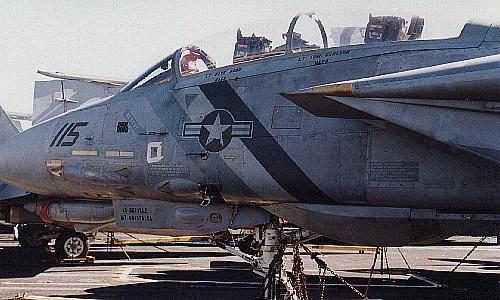
3. Forward Fuselage
|
NACA style gun vents on a VF-2 F-14D. Image Courtesy of Rodger Kelly |
4. Main Body
Attach the main body halves, lower and upper. There are several
spots here that either don't fit perfect or are tough. Careful fitting,
some sanding and putty will be required.
Before attaching them look at the directions; there are a couple
of parts to add. Also remove the raised 'sink hole' imprints from the main
gear bay wells. If you're going to superdetail the landing gear bays, sand
away all the wire detail from the upper body half. Save pieces D21 and D20
until after adding the intakes. They will be harder to position, but there
placement will be in the right place.
Assemble the boat tail now. There are two options, one with the
ECM bump and one without. Almost all fleet airframes have the ECM bump.
VF-24 on it's last cruise took three jets that didn't have it, so they are
still in the fleet, but they are the exception. This ECM bump is also on
ALL F-14B and Ds. If you want the speed brakes closed, glue them before
assembling the boat tail halves. Glue them from the inside. The trailing
edge of the top speed brake should sit up off the tail, not flush. Drill
out the fuel dump port and paint the interior flat black. The exterior can
either be the gray of the airplane or red. Often drilling it out will
collapse the plastic. Don't worry this can be a good thing. Replace it
with brass or aluminum tubing cut to the correct angle. Better to find out
now about the frailties of the model then after you're finished.
The chaff/flare boxes also need to be addressed. Hasegawa provides
photo-etched covering and if you are modeling a bird that is on cruise or
engaged in live weapons armament then using the piece is fine. If you're
model is stationed at a naval air station or not engaged in combat or live
combat training, then they won't have these pyrotechnics installed. Before
gluing the boat tail halves together, drill the box area out. Then with
styrene strip box it in, keeping the inner box construction not quite to
the level of the tail's surface. Split the rectangle into two squares with
a dividing piece of styrene. These empty 'boxes' are painted yellow zinc
chromate. A perfect match is Testors zinc chromate (in the small bottles)
with a drop of orange.
In assembling the main body, work from the aft end forward,
fitting the boatail first. I usually glue the aft end one day, let it set
and then glue the front end. With some fiddling you can get the boat tail
to fit properly. If you can't, be more concerned with the upper side
lining up than the lower. The lower side will be canted upwards slightly -
this is fine.
Where the aft fuselage comes together there is some extra overhang
of plastic from the lower half. Don't worry about it right now. If you can
hold the model in the right shape for it to set properly then you're ahead
of the game, and doing better than I usually do. The excess is cleaned up
by some putty and sanding. There can be overhang as well under the wing
sweep pads. I've easily removed it by carving it away with an X-acto knife
and then sand it smooth.
Try not to glue the glove vanes. If you have to glue them, putty
the seam and inscribe a new lines later or use ink to draw them in.
Depending on the condition of the body halves, such as any warping it may
be necessary to glue the glove vanes. The area aft of the glove vanes
could use some putty and sanding just to make the seam smooth. I like to
run superglue along the inside of this seam for additional structural
strength.
Chose the wing positions you want now, because you'll want to glue
the wing pads soon. Be aware that you have to cut a pin to position them
in the oversweep position. There are two choices given: forward or
oversweep. The wings are not hinged but slide in easily so they can be
added after painting. I have modified the wings so they pivot separately
on a post - for an inflight model. Also be warned that the port side wing
root (that's the left side if you are looking down on the model) needs to
be slightly reshaped if you want the wings forward. Somehow, the wing and
the wing root don't match up. You could also sand down the area of the
wing bubble that fits there. If not addressed, the wing bubble will chip
the plastic when you have to force it into position.
Smooth the joint under the forward lip in front of where the
intakes will go. This will be difficult to do once the intakes are
attached.
One last step on the upper half of the main body; Hasegawa molded
mounting stubs for antennas and they should not be there. Using a sharp
blade cut them off and smooth the area with light sanding. The center of
the three antennas is molded in with the stub. It is too thick anyway, cut
the whole thing off. Replace it with a piece of scrap photo-etched metal
or a thin styrene strip. Use E26 for the forward most antenna, not E28
like the instructions indicate. This was part of the update when they got
the new gun vents. Add these antennas just before painting.
Before attaching the vertical tails, test fit them. I've found
that they need a little scrapping and filing to fit perfectly with the
mounting section. This also goes for the vertical strakes on the
underside. A little care can create the perfect fit and prevent filling
seems.
5. Intakes
Sand and smooth the sink holes of the intake trunks. paint the
front engine fan steel and give it a black wash to accentuate the blades.
If you want the blades spinning try filling in the blades with GS HypoTube
cement after or before painting. Both ways give an outstanding effect. I
paint the fans silver if I do this to reflect the light; it helps the
effect. Assemble the intake trunk and paint flat white. There are two
styles of interior paint, one is a straight demarcation all the way around
the inside of the intake of gray to white about a foot back from the lower
intake lip. The other is more complicated; it has the bottom demarcation
as above, but four inches up is becomes a diagonal that goes back to just
aft of piece E2.
You can make stylized intake covers from tissue soaked white glue.
I've never liked that method, so I made a template of the intake covers
and cut them out from sheets of Ken's Kustom Kar simulated leather. It is
a perfect match of the vinyl covers that the squadrons use. It is an
adhesive backed sheet and easy to cut. I paint the stylized markings of
the squadron onto them before cutting it off the backing sheet using a
template.
The intakes can be tricky to install. Work from the back to the
front. I trim the aft mating section slightly to achieve a better fit.
This is time consuming; holding them in the appropriate positions - they
just don't seem to want to always stay. Take your time and have patience.
It will be rewarded. Having a third hand would be helpful, so I often
employ the help of whoever else is at home. I hold, they glue.
6. Pylons and Weapons
Here it is time to decide on what the weapons load out will be, or
if you want to add weapons. Because the kit doesn't come with any, you'll
have to get them from other sources. I use the Fugimi missiles. Many of
the aircraft today are often seen with the bomb racks under the forward
phoenix pylons. Aft phoenix pylons are only added if they are going to be
used. Shoulder pylons common now are sparrow and sidewinder on the one
side, phoenix and sidewinder on the other. Lantirn pods go on the
starboard shoulder, 8B. If you use the Tarps pod, be sure to put on the
forward phoenix pylons. They have to counterbalance the weight to the pod,
2000 pounds. On shore stations, they also used cement filled sparrow body
tubes (without the fins), painted blue. All birds at sea will have the
drop tanks; if it's on land, your choice.
The forward phoenix pallets need to have the mounting pins and
stub removed, these will only get in the way. Position them so that the
front tip extends past B7 1/2 millimeter.
When assembling the drop tanks, you're going to need to do some
puttying and sanding of the two halves. For the aft end, putty over the
piece and sand it flat. It should be a flat vertical surface. I like to
use the Fugimi drop tanks, but these need a little putty on the seams as
well. They are split into sides, rather than the Hasegawa's which are
split into upper and lower halves. The aft end has a bubble which should
be sanded to a flat vertical surface.
Most missiles are painted in FS 36375. Sidewinders still have
black noses, sparrows and phoenix often have an off-white nosecone. Live
rounds have stripes of yellow and dark brown. Look at pictures. Some
phoenix are still painted overall white. An effective way of simulating
the seeker head of the sidewinder is to dip the nose into silver paint
after it's finished. Consider replacing the after fins with the
photo-etched kit from Model Technologies sidewinder fins. One correction
to the Fugimi phoenix missiles is to add the inner exhaust ring. Use a
1/8in size tube. Thin it and glue it into the exhaust section.
The Hasegawa Tarps pod is more accurate than the Fugimi one. I've
had convincing results painting the inside of clear pieces gloss black.
Painting on the inside gives the lens added depth. You will need to add
stabilizing fins 3/4 of the way back on the lower vertical part of the
body. Look at current pictures of the real thing. Squadrons often stencil
their insignias and VF number on them. The markings are usually the same
as the drop tanks. (ie - VF-31 paints the Felix the cat markings from
their drop tanks on the Tarps pods) If you do a diorama of the bird in the
hanger, consider adding a Tarps pod on a stand to the scene. Here is where
you can cut it open and detail the interior as well as the mounting area.
All the squadrons left in the fleet have Tarps capable aircraft.
Improve the sidewinder rails by taking a thin file longitudely and
sand the center out. This leaves an upper and lower rail. You could make
rails by gluing thin strips of styrene. Paint it lightened black.
The F-14 can carry the full range of Mk80, Mk20 series bombs. They
carry the 5-25lb training 'blue' bombs on TERs(triple ejector rack) as
well as the TALDs Tactical Air Launched Decoys) on the TER. (I haven't
seen any TALDs in 1/72 scale. The fleet is now acquiring a new, smaller
TALD.) The Tomcat can also carry the laser guided training rounds and all
forms of GBU laser guided bombs. Tomcat's can drop laser guided weapons
with the new Lantirn pod, or without the pod if the target is lazed by
another source, air or ground. Tomcat's from VF-41 dropped guided bombs on
targets in Bosnia that were lazed by Hornets. CAG 9 Tomcats worked closely
with the Marines at TwentyNine Palms developing tactics and a working
relationship for the CAS (close air support) roles. More on the Lantirn
and guided weapons in a later section.
As for the bomb racks, Hasegawa has a set of four in the Bomcat
kit, SP97. Fugimi has a set of four in their Bombcat I and Bomcat II kits.
Neither is a perfect representation, but either will work. I scratchbuild
my own because I like to.
A final note - the F-14 does not and will not carry the AIM-120
AMRAAM. (the kit instructions show it). Other weapons that were
considered, and had some form of testing done but will not be implemented
include, HARM, Maverick, Harpoon and rockets. (I've seen a VX-4 bird
loaded with a Harpoon on the starboard shoulder pylon for static
testing.). It was decided that the AIM-7 Sparrow was a capable enough
weapon for the F-14 platform. That coupled with the AIM-54 Phoenix
capability was seen as adequate. There is still a debate about the need
for the AIM-54 system currently, but it looks like the F-14 will continue
to carry the Phoenix throughout it's lifespan.
7. Painting, Markings, and Decals.
I've spent a lot of time trying to figure out the perfect way to
replicate the TPS. Using the straight colors comes out too dark,
especially with gloss and flat coats over the top of them. I've been
experimenting and trying to get it right for a lot of years and finally
come up with what works for me. I learned an excellent piece of advice
from a fellow naval aircraft modeler, "Don't worry about it!" This is
true. Paint and weathering is as diverse as each airframe. The variations,
lighting conditions and touch-ups can make the paint job very diverse.
Depending on the lighting and sun angle, one plane can appear to be
painted different colors at different times of the day.
Take into consideration the markings. Do you want the stenciling
to be very visible, dark or light colors, etc. Many of the current TPS
machines use the upper surface color for most of the stenciling, national
insignias, ejection seat triangles, warnings, etc. Look at the decals you
are going to use and check the photos of the specific plane you are
modeling. If you are doing a general model, not a specific airframe, or
out of the box then follow the instructions. On a recent specific
aircraft, I made templates for the general markings and painted them on. I
painted the squadron markings as well. It was time consuming work, but the
results were worth it and I have a unique model.
I found several ways to make good templates: 1- photocopy the
decals, and cut out them out from the paper. I like to use gloss paper
because it repels paint instead of absorbing it. 2- using low stick scotch
tape, place the tape over the decal and cut out a template. Gently lift
the tape and apply to the model. It's possible to damage the decal itself,
so I recommend the first method.
Here are the mixtures I use for the Tactical Paint Scheme:
Underside: 3:1 light gray to light ghost gray
Middle: 1:1 light gray to light ghost gray. 1 drop intermediate blue per
paint cup
Topside: 5 parts light ghost gray, 3 parts light gray, 1 part intermediate
blue
After airbrushing each coat I let it dry for 15-30 minutes and
then lightly rub it down with a soft rag. Cotton balls, a soft T-shirt or
a paper towel will also work. If you push too hard you can rub through
the still not dry paint. This as a couple of effects: it smoothes the flat
paint and also imparts a shiny, metallic like sheen to the high points,
giving the model a 'heavy' look. After the paint has fully dried I wet
sand it starting with 800 grit and working up to 4000 grit sandpaper. This
fully smoothes out the paint giving it an almost polished smooth surface
usually adequate to apply decals to. It rids the model of any paint
blemishes and dust that might have accumulated during drying. (Around here
dust is a big problem). You could use a polishing compound as well or use
gloss coat, but this technique works well for me. I leave some of the
sanding dust to dry on the plane. I clean it off if it is to thick;
accumulating in the panels lines or someplace I don't want it, but fairly
often the dust dries and helps to weather the plane. If I want to keep it
I seal it in with a shot of semi-flat coat and sand it smooth. . You only
need to be really concerned with the smoothness of the area that the decal
will go, but you want the surrounding area to look uniform.
If you go the gloss coat route I recommend using Future Floor Wax.
Test it first because it has a tendency to be pebbly or orange peel if the
pressure isn't right. 20psi usually works well for me, and I shoot it
through the airbrush straight out of the bottle.
8. Weathering
I have developed a technique for defining panel lines called a
"pre-wash". This coat will be the first one applied to the airframe. Wash
the plane thoroughly with soap and water. Shoot a coat of a mixture
consisting of black, brown and maybe a little green depending on the color
you want the panel lines. Thin it liberally so it's basically a thick
wash. You want to get it into the panel lines. When you apply the main
coat, do it in light misting coats. The base "pre-wash" will show through.
If the subsequent coats of the paint scheme cover it up completely then
lightly scribe on the panel lines to scratch away the top paint coat.
After the model is completely painted and decaled, I apply washes
of various colors: black, brown, gray. I also use pastels for weathering
the paint and showing dirt and grime. You can also use oils, but my
experience with them is limited. I have experiemented with water colors
and have had some very good results. You can vary the strength of the
color by how much you dilute them, and if you make a mistake just wash it
off and start again.
I do use pastels to replicate the non-skid surfaces on the top
fuselage, aft of the cockpit. I make a template from the decal, and dust
on think coats of pastels. I've also done this by spraying paint non-skid
on with a spray can. Stiple the paint with an old, stiff brush before it
dries to give it the rough, pebbly look.
9. Landing Gear and Landing Gear Bays
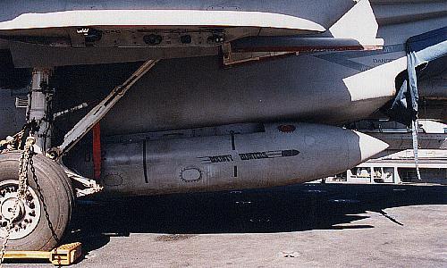 |
Main gear and drop tank of a VF-2 F-14D. Image Courtesy Rodger Kelly |
10. Exhausts
First, remove the mounting pins from the interior of the tubes.
With a sharp knife and some careful sanding this is pretty easy. Fill in
the resulting hole with putty and use a shaped file to induce the pattern
on the tubes. Glue the tube halves and paint sand. Give it a dirty, but
light black wash. Put the exhaust streaks in with something between
drybrushing and straight painting, I call it a heavy drybrush. I counted
25 streaks from the exhaust fans. Assemble the exhaust fans and paint
black mixed with sand. Assemble the rest of the exhaust section and glue
to the main body before painting. This is because the fairing M3 and M4
might need a little putty to fair in smoothly.
Achieving convincing results on the exhaust petals is fairly easy.
Keep in mind there are a lot of variations due to weathering and condition
of the engine. I like to paint them Dark Anodonic Gray (Testors Model
Master Metalizer). Seal that and then add a flat coat. Give the petals (F1
or F2) a wash of black mixed with Testors Rubber. I usually give them a
dusting of black, gray and brown pastels. For the closed petals (F2), give
them a thicker coat of black pastels. I give the same treatment to the
inside of the petals.
11. Clear parts and Canopy
The instructions call for the starboard wing and glove vane lights
to be painted clear blue. Everyone always says paint them clear green. The
lights are green, but when they are off, they have a bluish tint. I split
the difference and mix equal parts of clear blue and green paint. I've
seen a guy used green and red LEDs and wire all the lights. Yes, this was
1/72! I tried it and failed miserably. The directions also call for the
center part of the windscreen to be painted clear blue. I use the above
mixture liberally thinned, so it doesn't have as much color to it and
paint the inside of the windscreen. This takes a little work to mask the
inside, but is very convincing.
When attaching the clear parts, test fit them first and sand the
attaching sides. This will help give the glue better adhesion. I recommend
GS HypoTube Cement for all clear parts.
The canopy has a serious mold seam. I cut it away with a sharp
x-acto blade, sand it down with fine sandpaper and polish it with "The
Final Detail" wax. Finish with a coat of Future Floor Wax. Then mask it
off and scuff the frames with a light sanding to improve the paint's
'grip'. The first coat of paint is black to get the frames inside the
correct color. Then paint the camouflage color. While it is still masked,
coat the paint with a shot of flat coat. This will seal the paint. I
highly recommend painting the canopy along with the rest of the model to
prevent a color distinction from mixing separate batches of paint.
I recommend cutting away the anti-collision light from the TVSU
and replacing it with a clear piece of plastic painted clear red or cut a
piece from a clear red toothbrush. For the later, a little bit of
polishing may be necessary, but it is very convincing in the end.
12. Inflight
I've already mentioned how to simulate the spinning of the front
engine fans. The modifications here are to the landing gear doors. Install
the front gear doors before assembling the fuselage halves. There will be
a gap in the center. Fill this with strip styrene, sand smooth and
re-scribe the line. It's a good idea to add a re-enforcing plate of
styrene inside the gear doors. This prevents them from 'pushing' in.
For the main gear doors, test fit first. The front main doors will
need to be trimmed to make a perfect fit. Put a chunk of clay into the bay
and use that to support the doors. The clay will hold them in place while
you glue them, and then provide structural stability.
If you want the wings to sweep, you need to do some additional
work, making a post assembly. If you are very innovative, you could take
the meshing gear from the Fugimi wings and transpose them onto the
Hasegawa wings. You might be able to use the Fugimi wings, just make a
post assembly for them to be seated on. I like the Fugimi wings better
than the Hasegawa ones. They fit better with the flaps and slats up. When
I do an inflight model, I pick what positions I want the wings in and
cement them in that position. If you want the wings in the swept back
position, you will need to do some minor surgery to have them fit with the
slots provided.
We already discussed the pilots in the Cockpit section, so all
that's left is mounting the bird. I recommend attaching the mounting rod
where the Tarps pod would go. If you want to be able to pick it up off the
base, make a supporting sheath inside the aircraft, so the mounting rod
will slip over it. Think this out before you assemble the main body
halves. Another option is adding a rod next to the tailhook, but this will
have to be a permanent attachment. One more good spot is between the
forward phoenix pallets.
13.B
Hasegawa has released several versions starting with the F-14A+,
and now they finally call it the F-14B. The Navy switched the designation
shortly after accepting the A+. The info I got from the Navy at the time
indicated that the change was based on the logistics software - it
couldn't handle the codes as F-14A+. I've heard different reasons over
time.
The changes over the F-14A airframe include: New GE F-110 engines
and fuselage fairings for them, a new ECM bump on port side front landing
gear door, ECM blisters forward of the glove vanes, and locked glove
vanes. When they were first introduced, the new spine antenna and gun
vents were new.
Most of the other changes were all internal and not a concern for
modeling.
To paint the GE engines I recommend using a 3:1 mix of gunship
gray and black on G2,G4. The aft lip of these pieces should be painted
silver. Also use this mixture for the recesses on the petals. The petals
bare metal color can range from silver to gunmetal depending on weathering
and condition.
The instruction sheet says to use parts J1, 2 - don't! Use the
vents J3,4.
14. D
I converted a 'B' into a 'D', but now that Hasegawa put out a
production 'D' (Vandy 1, VX-9 overall black) the conversion might not be
necessary. I haven't seen the kit yet, and don't know if it includes the
additional necessary changes from the 'B' kits: ejection seats (Use the
True Details NACES seats. Add large canopy breakers to the pilot's seat),
new cockpit displays (I know the sprue of the 'B' kit has the HUDs), the
means to have the wing glove vanes sealed. This is actually pretty easy,
install the glove vanes and putty over the seams, sand smooth - viola! The
new TVSU/IRST undernose sensor pod should be included because the 'B'
sprues have the IRST seeker head.
The 'D's do NOT have the ECM bumps along the intakes (something
the F-14 Walk Around book says they have), but they do have the ECM
blister on the boatail. Some other differences are new pilot and Rio
control sticks, the box on top of the Rio's instrument panel coaming and
finally the small circular ECM blister on the back of the starboard
vertical tail. This can be easily added with a piece cut form a plastic
rod. Also the forward bulkhead of the front landing gear bay is different.
A final detail is to add a formation strip light under the ALQ-100.
After saying I wasn't going to cover the conversion, I think I
just did.
Note: Hasegawa released the prototype variant and an early version
of the F-14D, but these were not reflective of the production version.
15. Lantirn
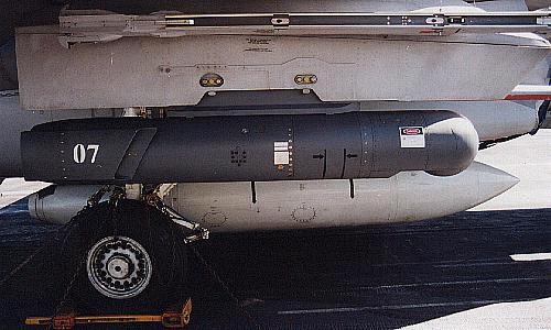 |
AN/AAQ-14 LANTIRN pod under the wing of a VF-2 F-14D. Image Courtesy of Rodger Kelly |
17. References
- Verlinden's F-14A/B Lock On.
- F-14 Walk Around. Squadron Signal. This is an excellent
reference, but be aware that it is missing some substantial things and has
a number of serious errors for the modeler. Here is a list of the errors,
corrections, and in some cases just clarification of their details that I
have found:
Those captions that have "Cannot tell it is F-14D" are for clarification. The detail shown in the photo is common for all F-14s.
The book jumps from calling the F-14A+ to the F-14B without any explanation. These are the same variant. They came into the fleet as the F-14A+, but were shortly re-designated as F-14B.
Page, Picture Location, Explanation
4. lower left. The F-14A/B does not carry an IR sensor
5. upper right. The F-14D has the APG-71 radar, NOT the AWG-9
10 lower left. This is a Top Gun bird and is an F-14A, NOT F-14A+.
Distinction being that the plane in the picture does not have the ECM bump
on the landing gear door that the F-14+ and F-14D have.(This is a good
place to mention that all F-14A/B/D have the NACA vents, post 1991).
16 far left. Really an F-14A from VF-213.
16 upper right. Photo is printed backwards
17 top. This Top Gun paint job was unique to that airframe, called the
"Powder Puff". In 1995 it was changed to a hard edged SU-35 Flanker blue
camouflage. Other Top Gun camouflage at the time was an Iranian painted
F-14A, and 2 standard gray F-14A's
17 lower right. This is a VF-2 F-14D
20 left. This is an F-14A front landing gear bay, NOT an F-14D. Note the
lack of the ECM wire junction box on the port side door. (see pg 21 lower
right)
20 right. Cannot tell this is F-14D
21 lower right. This has to be either an F-14B or an F-14D
21 upper left. This has to be either an F-14B or an F-14D
25 upper right. Cannot tell this is F-14D
37 lower left. Cannot tell this is F-14D
38 left. All F-14A/B/D now in fleet have this ECM bump on the boatail.
Only older F-14A airframes lacked it, those are now all out of fleet
service.
39 bottom 3 pictures. Cannot tell this is F-14D
40 upper right. Clarification; both port and starboard have the aft end of
the ventral fin uncovered
31 upper left. Cannot tell this is F-14D
43 top pictures. Clarification; both ventral fins have the vent on the
port side.
43 lower left. This is NOT an F-14D. These ECM bumps are internal on the
'D' where the glove vane used to be. Note the glove vane is present in
photograph.
44 upper left. Cannot tell this is F-14D
52. Fails to identify engine as F-110 of F-14D
57 lower right. This antenna is common for all current F-14A/B/D, post
1991
66 upper left. This is the pilot's flight control stick, NOT the Rio's
controller
68 lower left. This is the Rio's (aft) cockpit, NOT the pilot's.
71 caption. The F-14A and F-14A+(F-14B) use the GRU-7A; only the F-14D use
the Mk MB-14 NACES
75 lower left. The F-14 does NOT carry fuel tanks on the phoenix pylons.
This is a luggage pod; an old A-4 drop tank converted to carry luggage and
items that would not fit aboard. Known as a "personal effects pod".
75 lower right. These were bomb racks tested, but are not representative
of the fleet used bomb racks.
76 upper left. This is a test bird with a bomb rack mounted on the
shoulder phoenix station. Fleet F-14s do NOT carry air to ground ordinance
on this station. Shoulder mounted phoenix pylons are more common now, with
the underbelly stations carrying the air to ground ordinance.
76 upper right. Same as above with the test bomb rack
79 upper right. This is an F-14A, NOT an F-14B. Top Gun had one very short
lived (2 months) F-14B in 1992.
80 left. This plane was painted for the Army/Navy football game. The
caption points out the "Go Navy" but fails to mention the "Beat Army"
written below it. This aircraft is actually from VF-14.
This book fails to cover the fleet bomb racks, spoiler detail (especially box interior), close-ups of phoenix and sparrow mounting rails and weapons, details of the Tarps pod, especially the interior and mounting plates.
This book was printed prior to the introduction of the Lantirn pods and associated cockpit improvements.
18. Product List
- Verlinden F-14 update set
- Eduard F-14 update set-designed for the Italeri/Testors kit
- Model Technologies F-14 canopy rails - have canopy and cockpit
sill rails, sidewinder fins
- True Details GRU-7A and Mk MB-14 NACES ejection seats.
- Evergreen styrene, sheet, strip, rod, etc.
- GS HypoTube Cement
- the treatment Model Wax - "The Final Detail"
- Squadron White Putty
- Future Floor Wax
-Tenex 7R
Super Scale International - decals
Pro-Stripe graphics tape
[Main Page] [F-14A] [F-14B] [F-14D] [Tomcat 21] [Atlantic Fleet Squadron Histories] [Pacific Fleet Squadron Histories] [F-14A Images] [F-14B Images] [F-14D Images] [F-14 Model Kits] [US Navy Air Wings] [A-6 images]